Engineering Reference
Rod End & Spherical Bearings
Staking Procedures
Staking is a method of installing a bearing with a V-groove into an assembly or housing. A V-shaped groove is cut around the face of the race, and the material outside of this groove is pressed into a chamfer of the housing with a staking tool. The information shared below includes step-by-step staking instructions, details on staking force, and a description of the v-groove staking tool design. Related topics are covered on separate pages and include typical installation setup, bearing installation, and bearing retention.
V-Groove Staking Procedure
Install bearing into housing and position it symmetrical about housing centerline within .005.
Mount bearing and top anvil over bottom anvil guide pin. (V-groove staking method)
A trial assembly should be made for each new bearing lot to determine the staking force necessary to meet the axial retention load required. Excessive force should be avoided since this may result in bearing distortion and seriously impair bearing function and life. (See table below).
Apply the staking force established by trial assembly, rotate assembly 90° and re-apply force.
After staking, a slight gap may exist between race lip and housing chamfer as shown in the detail. This gap should not be a cause for rejection providing the bearing meets the thrust load specified.
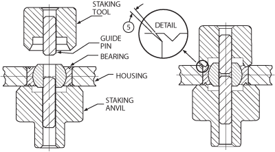
V-groove staking method.
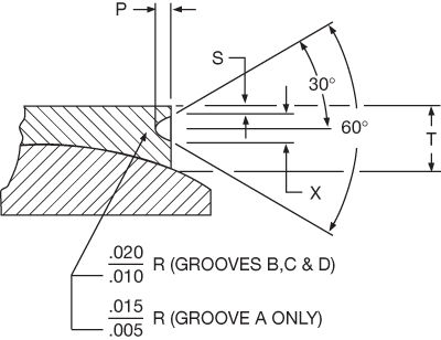
V-groove sizes.
V-Groove Size and Force Data
| V-Groove Size | P | S | X | T | Staking Force Lbs |
|---|---|---|---|---|---|
| A | .030 | .020 | .045 | .075 | 7,700 |
| B | .040 | .030 | .055 | .125 | 12,000 |
| C | .060 | .030 | .080 | .156 | 17,700 |
| D | .080 | .045 | .105 | .188 | 25,800 |
*For PTFE lined bearings, add single liner thickness to "T Min.".
Staking Force Requirements
The staking force equals the product of the bearing O.D. and a constant for each groove size (see table above). For example, for a bearing with a “B” size V-groove and 1.500 O.D., the staking force will be 1.500 X 12,000 lbs. = 18,000 lbs.
These staking forces are valid for outer race materials having an ultimate tensile strength of 140,000 psi.
Staking forces for other materials are proportional to the ultimate tensile strength or the materials as compared to 140,000 psi.
These staking forces should be used as a general guide to establishing a starting point. Lower forces may be adequate or higher forces may be necessary depending on staking technique and axial load requirements.
As a rule, only the amount of force required to get the desired amount of retention should be used.
The use of proper fits and staking techniques should not cause significant changes in bearing preload.
As a minimum, the first and last article staked should be proof-tested. A method for proof-testing staked bearings for axial retention is shown below. This is the generally accepted method for checking retention that bearing and airframe manufacturers use.
The graph below shows allowable design thrust loads for bearing O.D.’s The loads shown should be obtainable using staking tools with 45° outside angles. Thrust Loads Based on Groove Types and Materials Specified.
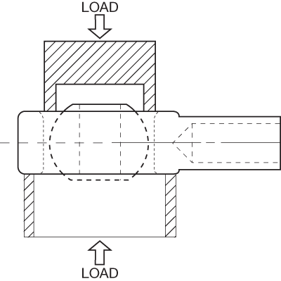
Staked bearing proof testing method.
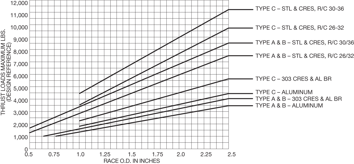
Thrust Loads Based on Groove Types and Materials Specified.
V-Groove Staking Tool
The staking tool and staking anvil depicted below are made from tough, hardenable tool steel (for example, A-2) and heat treated to Rc55 to 60. The critical dimension of the tools are as listed. As a final check on the staking tool and anvil, a final layout drawing should be made to check fit-up.
Staking Tool Design
B = Bearing O.D. - 2 X min. lip thickness - min. groove width (tolerance + .005/ -.000).
C = Adequate stakes for most applications are obtained with staking tools having 45° to 50° outside angles. When required, secondary staking tools having an outside angle of 60° to 70° can be used to obtain maximum retention and to reduce the amount of gap between the housing chamfer and the lip of the outer race.

Staking tool design.
Staking Anvil Design
A = Ball bore min. -.001 (tolerance + .000/ -.001).
B = √(spherical diameter2 - race width2) + .030 (tolerance +/- .010).
C = √(body head diameter2 - body width2) (tolerance +/- .010).
D = (Ball width max. - race width min.)/2 + .015 (tolerance +/- .010).
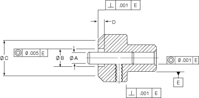
Staking anvil design.