Engineering Reference
Rod End & Spherical Bearings
Self-Lubricating Liner Systems
Self-lubricating plain bearings incorporate a liner that includes polytetrafluorethylene (PTFE) on the bearing surface. Selecting the correct bearing liner system requires an analysis of an application's load, temperature, speed of oscillation, and the directional nature of the load. During use, PTFE transfers to the mating ball surface, forming a lubricating film that is continually replaced throughout the life of the liner material.
Characteristics of Self-Lubricating PTFE-Lined Bearings
Modulus of elasticity: 4.5x10⁵ psi.
Coefficient of thermal expansion: 11.6x10⁻⁶ in/in/°F.
Low coefficient of friction ranging from approximately .02 to .10. The coefficient decreases as load and temperatures increase (see chart). However, the coefficient also increases as surface speed and mating surface roughness increase.
Non-corrosive.
Resistant to most chemicals, greases and oils, however, wear rates may increase when movement takes place under contaminated conditions.
Non-conductive and non-magnetic.
Wear rates remain low and relatively constant after an initial run-in period.
Continues to function satisfactorily with wear as high as .010.
Construction Types
NHBB uses four basic constructions for PTFE liner systems: laminates, woven materials, metallic-backed composites, and a homogeneous composite material. The woven materials can be combined with proprietary ball coatings to provide additional performance benefits. Each PTFE liner system (except the DU®,which is mechanically retained) is bonded to the race surface. During use, PTFE transfers to the mating ball surface, forming a lubricating film that is continually replaced throughout the life of the liner material.
PTFE liner systems can also be applied to customer-supplied parts. Flat surfaces, cylindrical O.D.’s, cylindrical I.D.’s, spherical surfaces, and special configurations are routinely lined by NHBB’s custom lining department by means of standard hard tooling or autoclave bonding.
Laminate construction.
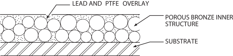
Metallic-backed composite construction.
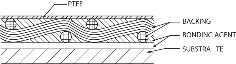
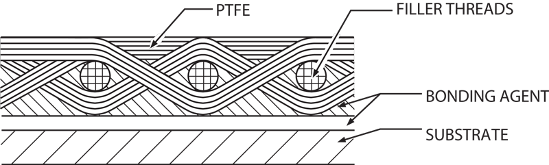
Woven construction.
Laminates
Laminates consist of an open weave backing fabric such as nylon, a porous PTFE bearing sheet, and a thermosetting phenolic adhesive bonding agent. The porous PTFE fabric is compressed into the backing fabric and impregnated with adhesive.
Metallic-Backed Composites
Metallic-backed composites consist of a steel backing, a porous bronze inner structure, and a PTFE and lead overlay. In addition to using bonding techniques, this liner type can also be mechanically retained.
Woven Materials
Woven materials consist of PTFE threads interwoven with high strength fillers such as nylon, Polyester or fiberglass threads. The majority of the PTFE threads are on the bearing surface while the high-strength filler material supports the PTFE and acts as a bonding surface. As with laminates, the adhesive agent is a thermosetting phenolic.
Homogeneous Composite Material
NHBB's homogeneous formulation, which is the basis for the Oscimax® brand of self-lubricating technology, consists of a proprietary matrix of thermosetting polymeric resins, PTFE, and various other compounds. Testing of this advanced formulation has demonstrated a performance breakthrough in self-lubricating liner technology. The liner coating is fully machinable from surface to substrate using conventional drilling, honing, milling, reaming, and turning techniques, enabling customers to achieve exact tolerances, better fits, and superior performance of the bearing assembly.
Surface Finish and Hardness Recommendations
Surface finish and hardness for the surfaces running against a PTFE liner are important for maximum liner life, whether on the shaft, ball, or other running surface.
For maximum life, NHBB recommends a finish of 8 Ra maximum, achieved by lapping, buffing, or honing after grinding. Anything higher than 8 Ra will reduce life.
Hardness should be Rc50 minimum. As hardness drops below Rc50, the mating surface begins to wear.
Torque
PTFE-lined spherical bearings are typically specified with preload between the ball and race in terms of no load rotational breakaway torque (inch-pounds or inch-ounces). This is the torsional force required to initiate rotation between the ball and race. Bearings can also be manufactured with a misaligning torque requirement.
The standard method for checking no-load rotational breakaway torque is described in Military Specification AS81820. The procedure is to hand-rotate the ball to initiate movement. Then the race is locked on a torque meter. The outer race is held in such a manner as to minimize bearing distortion and the resultant effect on the bearing preload. Torque is gradually applied to the ball. The torque required to start the ball moving is then recorded.
NHBB uses the same method to check torque, except that the ball is locked on the torque meter and the race is rotated.
Breaking the ball free from the race before checking torque is very important. Because of preload between the ball and race, the liner, under compression, slowly conforms to the microscopic surface irregularities of the ball. To initiate rotation after a period of time, all of the microscopic liner projections into the ball surface must be sheared off. Once this has been accomplished, the torque reverts back to its rated value. All torque testing should be performed with the outer race restrained in such a manner as to minimize bearing distortion and with the resultant effect on the torque reading obtained. Torque readings can vary appreciably as the result of incorrect or excessive clamping, presence of contaminants, excessive speeds and differences in atmospheric conditions.
Rotational Breakaway Torque is the highest value attained just prior to ball movement. The ball should be hand rotated through several revolutions immediately before testing.
Rotational Torque is the value required to maintain 2 rpm rotation of the ball about its centerline.
Misalignment Torque is the value required to move the ball in a mode other than rotation about the bore centerline.
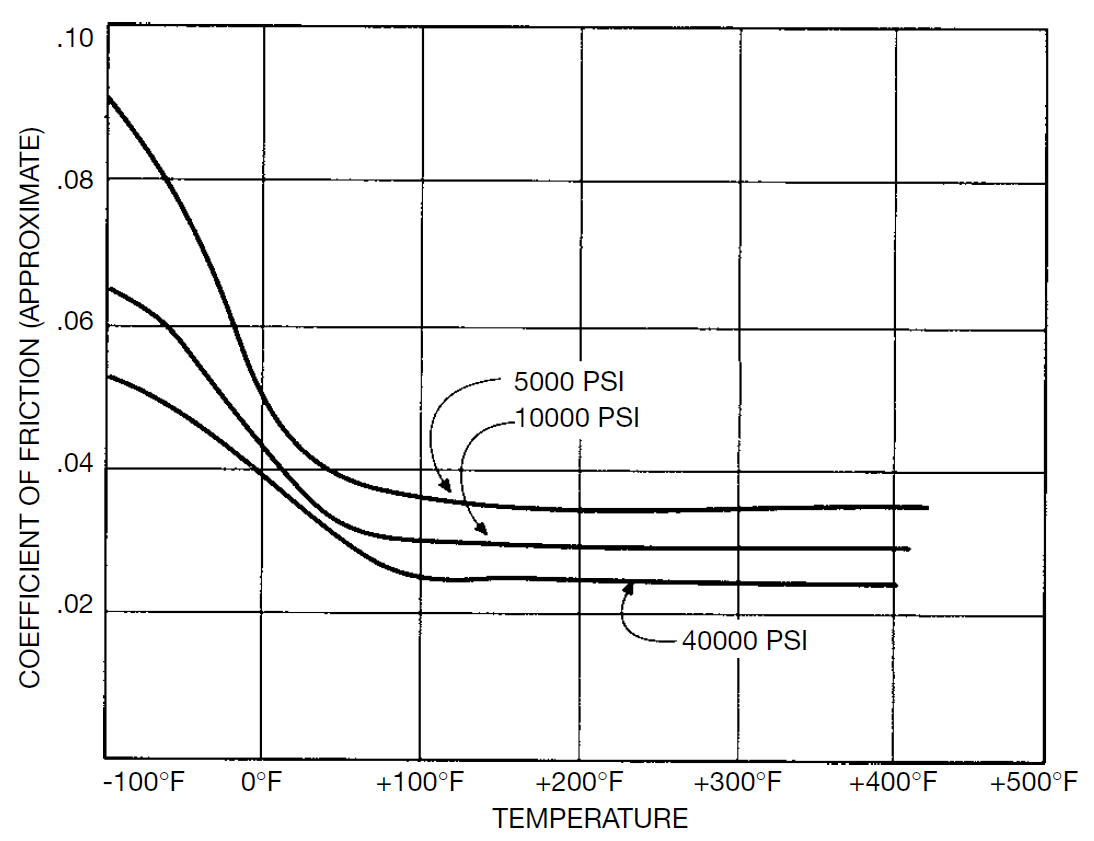
The effect of temperature and load on coefficient of friction.
Calculating Torque
The prediction of spherical bearing torque is more difficult than that of rolling element bearings. Friction coefficients (see table above) of the sliding surfaces in these bearings vary depending on temperature and load. Torque at various loads is estimated by using the following formula:
T = µ x F x R
Where:
T = torque, lbfin
µ = friction coefficient
F = load in lbf
R = one-half of ball diameter for spherical bearings turning on ball; or one-half the bore diameter for plain journal bearings or spherical bearings turning on bore.
Gaging Lined Bores
Conventional bore measuring equipment such as air gages and inside micrometers will often indicate an apparent oversize condition when used in measuring fabric-lined sleeve bores. Texture and resiliency of the fabric liner, as well as the contact pressure exerted by the gaging instruments all contribute to the probability of obtaining a false reading.
The most widely accepted method for inspecting lined sleeve bores is with the use of functional plug gages (see below). The diameter of the “go” member should be the minimum bore diameter specified and that of the “no-go” should be the maximum bore diameter specified. The “go” member should enter freely or with light to moderate force. The “no-go” member should not enter with light force but entry under moderate to heavy force is acceptable.
All edges of gage members should have a radius of .03 minimum, and surface finish of the gage should not exceed 8 Ra in order to prevent damage to the fabric when inspecting.
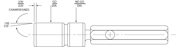
Plug gage.
NHBB's Self-Lubricating Liner Systems
As the table below illustrates, NHBB offers more than a dozen different types of PTFE liner systems in four basic constructions. What follows is a brief description of the most common systems. For more information, please contact NHBB Astro Division's applications engineering department.
Table of NHBB's Self-Lubricating PTFE Liner Systems
Please Note: This table does not contain information about three of NHBB's most advanced liner technologies: Oscimax®, INVINSYS®, and Vulkyn®. For information about these solutions, please review the brief descriptions at the bottom of this page, follow the links to the individual landing pages, or contact NHBB.
| Liner Type | Model | Construction | Thickness | Temp. | Static Limit Load | Typical Performance | Dynamic Capabilities | Typical Uses | Comments |
|---|---|---|---|---|---|---|---|---|---|
AD/AD (L) or AK | L-1291/ L-1420 | PTFE/Nylon Laminate | .010-.012 | -65° to 400°F | 75000 psi | 37500 psi At ±25° and 10 cpm, .0045 wear max. at 25000 cycles | Light to heavy, uni-directional or alternating loads. Low speed, intermittent to continuous misalignment, intermittent to continuous oscillation | Fixed wing aircraft, rotary wing aircraft and jet engines. Control, support and actuation bearings | Intermittent use to 500°F |
K | X-1820 | PTFE/Nylon Weave | .013-.015 | -65° to 400°F | 75000 psi | 37500 psi At ±25° and 10 cpm, .0045 wear max. at 25000 cycles | Light to heavy, uni-directional or alternating loads. Low speed, intermittent to continuous misalignment, intermittent to continuous oscillation | Fixed wing aircraft, rotary wing aircraft and jet engines. Control, support and actuation bearings | Intermittent use to 500°F |
D | L-1276 | PTFE/Polyester Weave | .013-.015 | -65° to 250°F | 75000 psi | Contact NHBB Engr. Dept. | Light to medium, alternating or reversing loads. Medium to High speed, intermittent to continuous misalignment, intermittent to continuous oscillation | Rotary wing aircraft and landing gear | Good stick/slip properites. Good for vibratory conditions. |
DD | X-1470 | PTFE/Polyester Weave | .016-.018 | -65° to 250°F | 75000 psi | Contact NHBB Engr. Dept. | Light to medium, alternating or reversing loads. Medium to High speed, intermittent to continuous misalignment, intermittent to continuous oscillation | Rotary wing aircraft and landing gear | Good stick/slip properties. Good for vibratory conditions. Extended life over D liners due to additional thickness |
HS | L-1340 | PTFE/Polyester Weave | .013-.015 | -65° to 250°F | 75000 psi | (Contact NHBB) | Light to medium, uni-directional loads. High speed, intermittent to continuous misalignment, intermittent to continuous oscillation | Rotary wing aircraft | DH (L-1480) liner offers same operating conditions but with a liner thickness of .018 |
AT | X-1118 | PTFE/Fiberglass Weave | .010-.012 | -65° to 250°F | 75000 psi | 25000 psi At ±25° and 10 cpm, .006 wear max. at 5000 cycles | Light, uni-directional loads. Low speed, intermittent to continuous misalignment, intermittent to continuous oscillation | Landing gear support and actuation bearings | Good stick/slip properties |
HT | L-1390/L-1550 | PTFE/Fiberglass Weave | .012-.014 | -65° to 625°F | 75000 psi | 12500 psi At ±25° and 10 cpm, .0045 wear max. at 25000 cycles | Light to medium, uni-directional or alternating loads. Low speed, intermittent to continuous misalignment, intermittent to continuous oscillation | Jet engine bearings and bushings | Recommended for long term high temperature use, 450° to 625°F |
DU® | PTFE/Lead Bronze Composite | .028-.030 | -65° to 550°F | 58000 psi | 5000 psi At ±25° and 10 cpm, .0030 wear max. at 25000 cycles | Light, uni-directional or alternating loads. Low to high speed, intermittent to continuous misalignment, intermittent to continuous oscillation | Rotary and fixed wing aircraft bearings and hinge bushings |
AD, AK and K Liner Systems
(Duraliners)
NHBB’s AD, AK and K liner systems consist of PTFE, flame-resistant fibers, and a thermosetting phenolic resin. The AD, AK and K liners are suitable for many fixed wing aircraft applications, such as actuators, hinges, and control bearings, where oscillation angles vary considerably but at slow oscillation speeds.
The AD, AK and K liners are qualified to AS81820 and AS81934. To qualify to AS81820, a lined bearing will be tested at room temperature for 25,000 cycles of ±25 degrees at 10 cpm and at 37500 psi. Maximum allowable wear is 0.0045. When tested at the elevated temperature requirement, the allowable wear is 0.006. When tested at -65°F, the load is reduced to 75% of the room temperature requirement, and the allowable wear is 0.008. AS81820 also has a test requirement for bearings to be immersed in various fluids for 24 hours at 160°F, removed from the fluid, and dynamically tested at 75% of the room temperature load requirement. NHBB’s AD, AK and K liners consistently exhibit less wear than specifications allow. Typical liner performance at ambient temperature is shown here.
The AD, AK and K liners are capable of operating for long durations when exposed to 350°F and short durations up to 500°F.
Tests reveal that the AD liner meets most vacuum outgassing requirements of space applications.
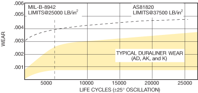
Typical performance of AS81820 liner systems (life cycles ±25° oscillation).
D and DD Liner Systems
NHBB’s D and DD liner systems consist of a PTFE and polyester weave coated with a thermosetting resin. The D and DD liners differ in the thickness of the liner. The DD liner has a liner thickness of .017 (Ref) and the D liner has a thickness of .014 (Ref). The additional liner thickness offers additional bearing liner life.
The D and DD liners were developed to accommodate alternating and reversing loads typically found in rotary wing applications where there are relatively low loading (approximately 2,000 psi) and the speed of oscillation is relatively high (approximately 300 cpm). Typical DD bearing life in a wet, reversing and alternating load test environment is shown below.
Current applications for the D and DD liners include landing gear shock struts, main and tail rotor pitch control link bearings, and damper bearings.
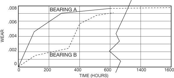
Typical DD bearing life in a wet, reversing and alternating load test environment.
Typical Performance of the DD Liner System (Reversing Load)
| Bearing | Ball Diameter | Race Width | Osc. | CPM | Stress | PV@ Max. Load | Contamination |
|---|---|---|---|---|---|---|---|
| A | 1.500 | .797 | ±10° | 300 | 0±2000psi | 26200 | Water |
| B | 1.500 | .797 | ±10° | 300 | 2000psi ±2000psi | 52400 | Water |
HS Liner Systems
NHBB’s HS liner system consists of a PTFE and Polyester Weave coated with a high temperature thermosetting resin. The HS liner has a thickness of .014 (Ref.).
The HS liner was developed to accommodate rotary wing aircraft applications in which high speeds (approximately 300 to 1500 cpm) and light uni-directional loading (approximately 2,000 psi) conditions exist.
The DH liner is available for applications similar to HS but requiring a thicker liner .018 (Ref.). For additional information, please contact NHBB’s Applications Engineering Department.
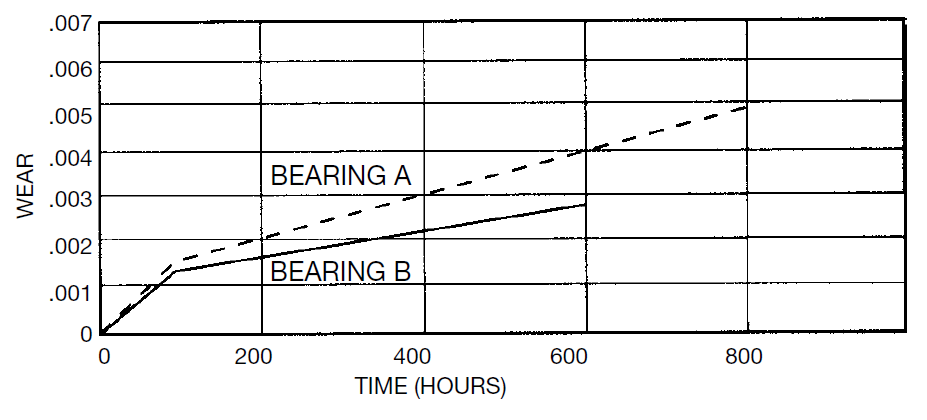
Typical HS bearing life in a wet, uni-directional load test environment.
Typical Performance of the HS liner system (uni-directional load)
| Bearing | Ball Diameter | Race Width | Osc. | CPM | Stress | PV | Contamination |
|---|---|---|---|---|---|---|---|
| A | .656 | .312 | ±6° | 1500 | 2000 psi | 34400 | Water and dust |
| B | 1.500 | .797 | ±10° | 300 | 2000 psi | 26200 | Water and dust |
High Temperature (HT) Liner Systems
NHBB HT liner systems are PTFE and fiberglass woven cloth that are impregnated with a high temperature polyimide resin. The HT liner is suitable for engine applications such as are found in variable stators for fans and compressors, throttle linkages, vane guide sleeves and actuators in and around the engine. These applications require liner systems that can accommodate temperatures up to 625°F. While the loading and motion are similar to fixed wing conditions, the high temperatures require a greater temperature resistant adhesive such as that used in the HT liners. The HT liner system is designed to meet higher operating temperatures but at reduced loads to those required for fixed wing applications (AS81820). The typical performance of the HT liner system at 12500 psi loading at 550 to 625°F at 20 cpm is shown here.
Typical performance of the HT liner system (oscillation under radial load, wear vs. life).
DU® Liner System
The DU® liner system consists of a low carbon steel sheet coated with a mixture of PTFE, lead, and sintered bronze. DU® lined bearings can be used in applications up to 550°F, but significant life-reduction factors must be applied.
Oscimax® Machinable Liner System
Oscimax® is a uniquely advanced machinable, self-lubricating liner technology developed by NHBB to reduce wear, resist corrosion and moisture, and extend the operating life of bearings and related mechanical assemblies. The patent-pending technology is a homogeneous formulation consisting of a proprietary matrix of thermosetting polymeric resins, PTFE, and various other compounds. Testing of this advanced formulation has demonstrated a performance breakthrough in self-lubricating liner technology.
The development of Oscimax® is ongoing and will evolve to include alternative formulations that offer specific performance characteristics (e.g., low friction), as well as additional applications like an injection-molded self-lubricating liner for spherical bearings. Visit the page devoted to Oscimax® for additional information.
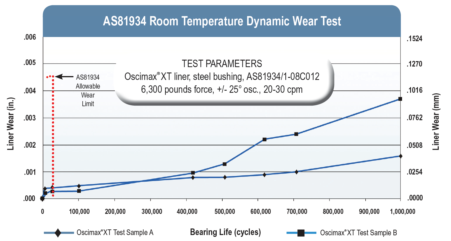
Results of AS81934 room temperature dynamic wear test.
INVINSYS® Self-Lubricating Liner System
The INVINSYS® bearing system consists of an enhanced self-lubricating liner paired with a specially coated ball that is engineered for superior wear resistance. This proprietary solution lasts up to two and a half times longer than previous designs tested under the same conditions. The significant performance advantage offered by INVINSYS® is helping to reduce maintenance and repair costs of helicopter pitch control systems. Visit the page devoted to INVINSYS® for additional information.
Vulkyn® Brand of High Temperature Self-Lubricating Liner Technology
NHBB's Vulkyn® brand of high temperature self-lubricating liner raises the maximum operating temperature of NHBB's high temp. solutions by 75°F. When tested to 700°F, Vulkyn® exhibits 0.006 in. of wear after approximately 150,000 cycles. At 570°F, the cycle count increases to 500,000 before wear reaches 0.006 in. Vulkyn® is also eco-friendly. The compounds in the fabric and bonding agents currently comply with REACH, which is an important benefit to many of NHBB's customers who supply product to European OEM's. Vulkyn® is ideal for both military and commercial aero engine applications in which bearings are exposed to sustained operating temperatures above 350°F. For more information, please contact the Astro Division or your NHBB field sales engineer.
Factors Affecting the Selection, Performance and Evaluation of PTFE Lined Spherical, Rod End and Sleeve Bearings
An answer to situations where the performance envelope cannot be covered by metal-to-metal bearings is to consider PTFE lined bearings. Here, the lubricant configuration is such that it functions as the load carrying element of the bearing, as represented by the liner systems currently in use. PTFE bearings may be specified under all or some of the following situations:
- Where lubrication is undesirable, difficult to perform, or impossible.
- Where loads are high and angular movement is low.
- Where space is limited.
- Where vibration is present.
- Where temperature of the environment renders greasing infeasible.
- Where a joint must remain static for an extended period of time before movement is initiated.
- Where friction in a greased bearing would be so high as to render the joint area useless after a limited number of cycles or impose an unacceptable fatigue situation.
- Where, in static joints, fretting is a problem.
While PTFE lined bearings can do an excellent job in many areas, there have been areas of misapplication. Also, there exist some misunderstandings regarding life and failure as applied to hardware of this type. Following are important clarifications concerning these products:
- The PTFE lined bearing starts life with a finite rotational pre-load torque or clearance.
- This rotational pre-load torque always decreases with bearing usage and clearance always increases with usage.
- A bearing may be said to have failed if the rotational pre-load torque drops below some specified value. This is always a systems application characteristic.
- A bearing may be said to have failed when the clearance generated by wear exceeds some specified value. This, again, is always some specified systems characteristic.
- A bearing may be said to have failed if the liner wears through enough to permit the ball to contact the race.
- No bearing, including PTFE lined bearings, will last forever. The “lifetime” lubrication concept applies to the bearing alone, not to the end usage item.
- The presence of liner debris on a bearing is not a definitive indication of failure.
- PTFE lined bearings tend to telegraph their impending failure by increased radial and axial play.
When evaluating the probable service life of a PTFE lined bearing application, there are some factors that do not appear in the PV = K relationship, (seePVFactor). Some considerations for a given application might include:
- Surface sliding speed
- Maximum ambient temperature
- Size of the heat sink
- Acceptable friction levels
- Load per unit of area, or liner stress level
- Mode of load application; i.e., the duty cycle
- Service alignment accuracy, particularly with respect to sleeve and flanged bearings
- Surrounding atmosphere
- Tolerable wear rate
- Surface finish of the bearing mating shaft and the shaft material
Cost is not included in the above list since it does not affect the serviceability of any bearing. Higher individual bearing costs may result in a more economical or lower priced finished assembly.