Engineering Reference
Rod End & Spherical Bearings
Load Ratings
The primary factors used to determine the load rating of a bearing include the dimensions and strength of a bearing's weakest component. When calculating load ratings, external factors, such as mounting components, pins, bolts, and housing, are not considered part of the bearing; you need to evaluate these elements separately. On this page, we explore the primary methods for calculating load ratings for spherical and rod end bearings, and we define PV Factor, a useful concept for comparing and predicting test results on high speed/low load applications.
Load Ratings of Spherical Bearings
The weakest part, or load-limiting area, of a spherical bearing is its race. For this reason, formulas have been developed that use the race to calculate static load ratings based on size and material strength. The static load rating formulas for self-lubricating and metal-to-metal spherical bearings are shown below. These formulas will yield approximate ratings, which should be used as ballpark numbers for bearing design.The allowable radial stress values given in the tables were determined from the ultimate tensile strength specifications for various race materials. Allowable axial stress values were derived from material yield strengths.
Load ratings for spherical bearings are calculated as follows:
Load = Projected Area x Allowable Stress
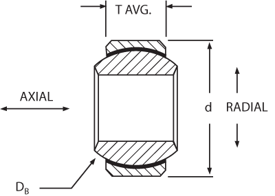
Radial Projected Area (RPA) = (0.91T)DB
Axial Projected Area (APA) = 0.636T2 – 0.05DB
Self-lubricating spherical bearings.
Metal-to-metal spherical bearings.
Allowable Stress for PTFE Lined Bearings (psi)
| Race Material | Radial | Axial | ||
|---|---|---|---|---|
Ultimate | Limit | Ultimate | Limit | |
| 17-4PH, Rc28 MIN | 112500 | 75000 | 67500 | 45000 |
| ALUM 2024-T351 | 60000 | 40000 | 36000 | 24000 |
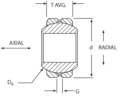
Standard Groove Sizes
| Bearing Size Bore Code | G |
|---|---|
| 3 & 4 | .062 |
| 5-10 | .078 |
| 12-16 | .094 |
| 20 & above | .109 |
Allowable Stress for Metal-to-Metal Bearings (psi)
| Race Material | Radial | Axial | ||
|---|---|---|---|---|
Ultimate | Limit | Ultimate | Limit | |
| 17-4PH, Rc32-36 | 150000 | 100000 | 125000 | 83000 |
| 4130 Rc32-36 | 150000 | 100000 | 125000 | 83000 |
| A286 (AMS 5737) | 140000 | 93000 | 95000 | 63000 |
| AMPCO® 15 Bronze | 75000 | 50000 | 45000 | 30000 |
AMPCO® is a registered trademark of AMPCO Metal Inc.
Load Ratings of Rod End Bearings
Rod end bearing load ratings can be generated only after carefully determining the load restrictions that each element of the rod end bearing imposes on the entire unit. In order to generate a frame of reference, consider the rod end bearing as a clock face, with the shank pointing down to the 6 o’clock position. The limiting factors in rating a rod end bearing are as follows:
- The double shear capability of the bolt passing through the ball bore.
- The bearing capability, a function of race material or self-lubricating liner system.
- The rod end eye or hoop tension stress in the 3 o’clock-9 o’clock position.
- The shank stress area, as a function of male or female rod end configuration.
- The stress in the transition area between the threaded shank transition diameter and the rod end eye or hoop.
Most rod ends will fail under tension loading in about the 4 o’clock-8 o’clock portion of the eye or hoop. The Net Tension Area (NTA) can be found as follows:
NTA=.008726 x D2 x Sin-1 ( T/D) + (T/2) x √(D2 - T2) – (B x T)
Solve the Sin-1 (T/D) in units of degrees, not radians.
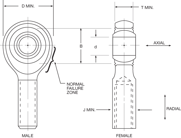
Male and female rod ends.
This simple rod end load rating formula does not take into consideration such variables as special body shapes, thin race sections, hardness variation, lubrication holes, grooves, and hoop tension, which could significantly affect the load rating. Contact NHBB Applications Engineering for assistance in determining the load rating for specially designed Rod Ends and Sphericals.
The shank stress area (SSA) is a function of being either male or female, as follows:
SSA = (minor thread diameter)2 x (π/4)
For the female: SSA = [J2 - (major thread diameter)2] x (π/4)
Pin shear stress (PSS) for load “F” is as follows: PSS = 2F/ πd2
The axial load capacity of a rod end is a function of the following:
- The retention method used to mount the bearing in the rod end eye (see the Bearing Installation and Retention section).
- The axial load capacity of the bearing element.
- The bending moment, if any, placed on the rod end.
PV Factor
While not a type of loading, the PV factor is very useful in comparing and predicting test results on high speed-low load applications such as helicopter conditions.
PV is the product of the stress (psi) and the velocity (fpm) applied to a bearing. Caution must be advised when considering extreme values of psi and fpm. The extreme must be considered individually, as well as together.
Because the PV factor is derived from the geometry and operating conditions of a bearing, it serves as a common denominator in comparing or predicting test results. For this reason PV values are included in the wear curves for liners in the Self-Lubricating PTFE Liner Systems section.
The formula for determining the PV value for a spherical bearing is as follows:
PV = (∞)(cpm)(DB)(psi)(.00073)
Where:
∞ = total angular travel in degrees per cycle (i.e. +/- 25°= 100° total travel)
cpm = cycles per minute (oscillation rate)
DB = ball diameter
psi = bearing stress
Dynamic Oscillating Radial Load
The dynamic oscillating radial load ratings given in this catalog for ADB, ADW, ADBY, ADB-N, ADW-N, ADBL and ADWL series self-lubricating spherical bearings are based on testing in accordance with AS81820. For conditions other than those specified by AS81820 contact NHBB Applications Engineering.
Load Ratings Terminology
The terminology and related diagrams found on this page will help you understand the different load rating concepts and formulas outlined on the Load Ratings page. The term misalignment is also defined here; a detailed description of this concept is on the Misalignment Capabilities page. If you need assistance with defining other terms not covered here, please contact NHBB's applications engineering department.
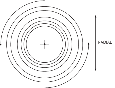
Radial Load: A load applied normal to the bearing bore axis (A).
Axial Load: A load applied along the bearing bore axis (B).
Static Load: The load to be supported while the bearing is stationary.
Dynamic Load: The load to be supported while the bearing is moving.
Static Radial Limit Load: The static load required to produce a specified permanent set in the bearing. It will vary for a given size as a function of configuration. It may also be pin limited, or may be limited as a function of body restraints as in the case of a rod end bearing. Structurally, it is the maximum load which the bearing can see once in its application without impairing its performance.
Static Radial Ultimate Load: The load which can be applied to a bearing without fracturing the ball, race or rod end eye. The ultimate load rating is usually, but not always, 1.5 times the limit load. Plastic deformation may occur.
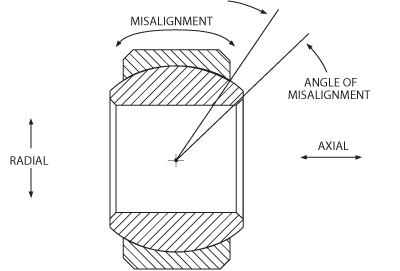
Radial/axial load, and misalignment.
Dynamic load.
Static Axial Limit Load: The load which can be applied to a bearing to produce a specified permanent set in the bearing structure. Structurally, it is the maximum load which the bearing can see once in its application without impairing its performance.
Static Axial Ultimate Load: The load which can be applied to a bearing without separating the ball from the race. The ultimate load rating is usually, but not always, 1.5 times the limit load.
Axial Proof Load: The axial load which can be applied to a mounted spherical bearing without impairing the integrity of the bearing mounting or bearing performance. It is always less than the static axial limit load. Bearing movement after proof load is usually .003 or less.
Rotation: Is the relative angular displacement between the ball and race that occurs within the plane perpendicular to the axis of the ball bore. The direction of rotation is about the axis of the ball bore.
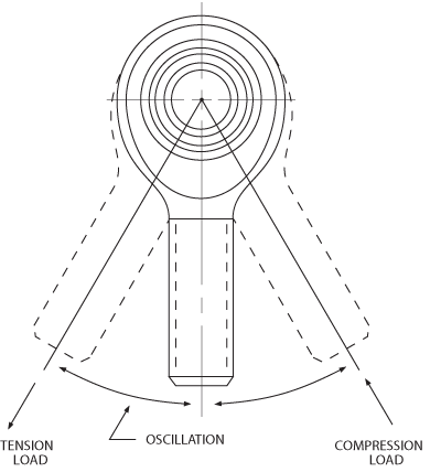
Oscillation.
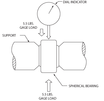
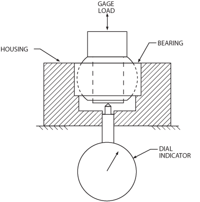
Method of measuring radial play.
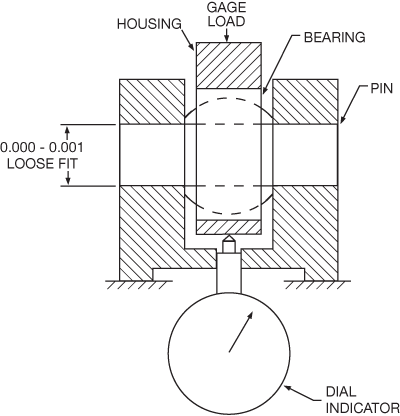
Radial test fixture.
Axial test fixture.
Misalignment: Is the relative angular displacement between the ball and race that occurs within any plane that coincides with the axis of the ball bore (see radial/axial drawing above). The direction of misalignment is about any axis perpendicular to the ball bore.
Oscillating Radial Load or Dynamic Load: The uni-directional load produces a specified maximum amount of wear when the bearing is oscillated at a specified frequency and amplitude. This rating is usually applied to self-lubricating bearings only. The dynamic capability of metal-to-metal bearings depends upon the degree and frequency of grease lubrication, and that of dry film lubricated bearings upon the characteristics of the specific dry film lubricant applied.
Radial Play: Radial play (or radial clearance) is the total movement between the ball and the race in both radial directions less shaft clearance (when applicable). Industry specifications have established the gaging load at ±5.5 lbs., and this is now considered as the industry standard. Unless otherwise specified, the industry wide standard for metal-to-metal spherical bearing and rod end radial clearance is “free-running to .002 max.” Radial play is sometimes referred to as “Diametral clearance.” The two terms are synonymous.
Axial Play: Axial play (or axial clearance) is the total movement between the ball and the race in both axial directions. The gaging load is again ±5.5 lbs. Axial play is a resultant, being a function of radial play, of ball diameter and race width. The ratio between radial and axial play varies with bearing geometry.
Fatigue Load of Rod Ends: Aerospace Standard series rod end bearings AS81935 must be capable of withstanding a minimum of 50,000 cycles of loading when tested as follows: The loading must be tension-tension with the maximum load equal to the fatigue loads listed on the NHBB drawing of the ADNE and ADN series rod end bearings. The minimum load must be equal to 10% of the fatigue loads.