Engineering Reference
Rod End & Spherical Bearings
Misalignment
Misalignment is an essential factor to consider when designing an assembly containing spherical or rod end bearings. It defines the relative angular displacement that occurs between the ball and race within any plane that coincides with the axis of the ball bore. Here, we illustrate how we specify misalignment for our catalog bearings, and we provide formulas for determining misalignment. Load Ratings, a closely related topic, is covered on another page.
How NHBB Specifies Catalog Bearing and Rod End Misalignment
The misalignment angle of a rod end or spherical bearing refers to the angle between the ball centerline and the outer member centerline when the ball is misaligned to the extreme position allowed by the clevis or shaft design, as applicable.
NOTE: Since angle “A” applies equally on both sides of the centerline, it follows that total misalignment of the bearing is double the value obtained for “A”.
The misalignment angle illustration shows how misalignment angles for standard ball spherical bearings and rod ends are represented in NHBB catalogs.
The misalignment angle is calculated per the Standard Method. Neck ball (high misalignment) bearings and rod ends are represented in the same manner, but are calculated per the High Misalignment Series Method.
NHBB prefers not to use rod end clevis misalignment for the following reason. The rod end clevis misalignment formula presupposes a clevis configuration as shown in which the clevis slot and ball faces are of equal width and in direct contact. In aircraft applications the configuration shown is more typical than that shown in the Rod End Clevis Misalignment illustration.
As pictured in the Typical installation, the clevis slot is wider than the ball to permit installation of flanged bushings and/or spacers. This results in a higher but more variable misalignment capability, and the angle of misalignment becomes a function of the user’s bushing flange or spacer diameter instead of the fixed rod end head diameter.
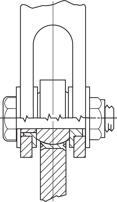
Typical rod end/clevis installation.
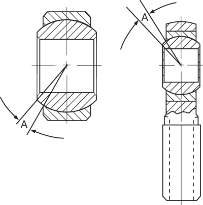
Angle of misalignment.
Formula for Determining Misalignment
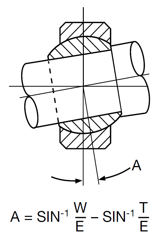
Standard Method. Most standard rod end and spherical bearing misalignment angles specified in NHBB catalogs are based on this method.
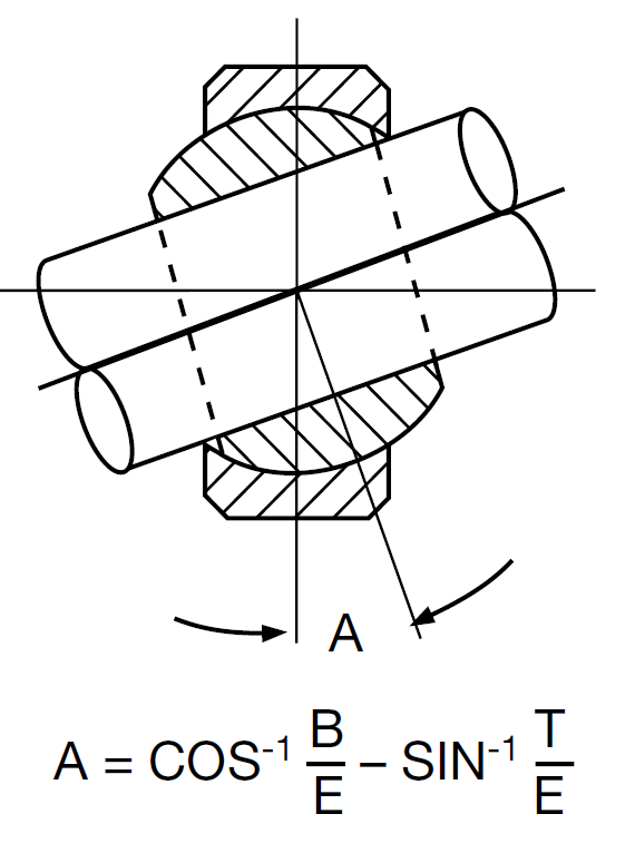
Design reference. This method may be used as design reference for installation purposes, but should not be used as a functioning misalignment under load.
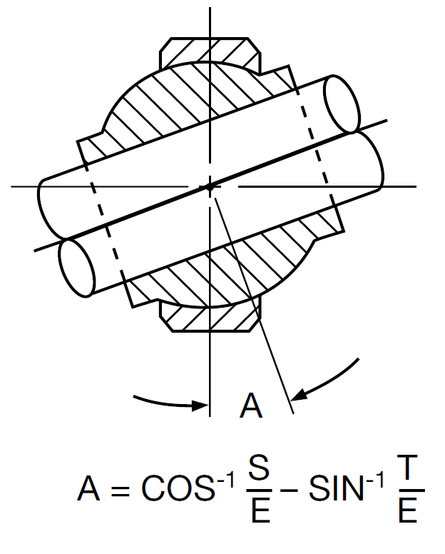
High misalignment series method (Neck balls only)
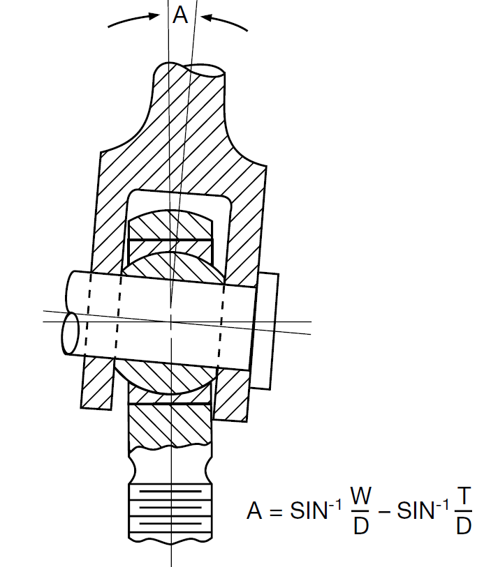
Rod end/clevis misalignment.
Symbols
A = angle of misalignment
D = head diameter (rod end)
S = shoulder diameter (neck ball)
W = width of ball
B = bore of ball
E = ball spherical diameter
T = housing (race) width

