Engineering Reference
Rod End & Spherical Bearings
Bearing Installation Procedures
The installation of a bearing or sleeve into a housing bore is a simple operation when done properly. Alignment of the bearing or sleeve to the housing bore is critical to prevent a cocking motion during insertion, which can damage or ruin the bearing or housing. Temperature differential installation is recommended. This page covers the installation of spherical bearings and lined sleeve bearings, provides some design guidelines related to pins, bolts, and housings, and discusses corrosion resistance. The related topics of staking and bearing retention are covered on separate pages.
Spherical Bearing
Use of an arbor press or hydraulic press is recommended. Under no circumstances should a hammer or any other type of shock-inducing impact method be used. A suitable installation tool (shown to the left) is advised. A guide pin aligns the ball in a 90° position, but all force is applied to the outer race face only. A lead chamfer or radius on either the bearing or housing is essential.
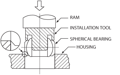
Spherical bearing installation.
Lined Sleeve Bearing
The same general procedure as outlined for spherical bearings should be followed. In the case of fabric lined bores, however, it is mandatory that both the insertion tool guide pin and the mating shaft have ends free of both burrs and sharp edges. A .030 (min.) blended radius or 15° lead is recommended, since it is virtually impossible to install a sharp edged shaft without inflicting some damage to the fabric liner. For maximum support of the fabric lined bore, the effective length of the insertion tool guide pin should exceed the sleeve bearing length.
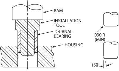
Sleeve bearing installation.
Typical Assembly
A typical bearing installation, which is staked into the housing, is assembled with a mating clevis, bolt, nut, washers, and plain and flanged bushings.In most applications, the bolt is preloaded with the nut to clamp-up the ball and force the ball to rotate on the race ID. Caution must be exercised when clamping the ball. Excessive force expands the ball and will bind it in the race. If the ball is not clamped up, motion will usually take place on the bore, in which case the bolt, the bearing bore, or both must have suitable surfaces for this motion.
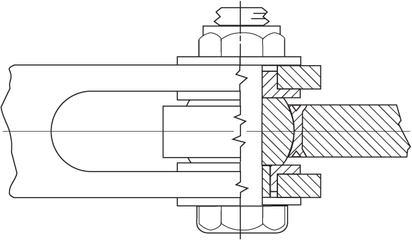
Typical bearing installation.
The Pin or Bolt
In addition to carrying the structural loads through the joint, the pin or bolt may function as a journal, and must therefore meet the multiple requirements of adequate strength, minimum wear, low friction, and corrosion resistance. In these instances, the following provisions for relubrication should be made:
- PTFE lines the bearing bore or the pin or bolt O.D.
- Dry film the bearing bore and/or the pin or bolt O.D.
- Introduce lubrication holes and grooves in the pin or bolt or the ball members.
Suggested pin materials are 17-4PH and PH13-8Mo stainless steel, and 4130/4340 steel chrome plated .002 in. thick. Pins, either bare or plated, should be heat treated to the required shear strength (108,000 psi Ref.) and ground and polished to the required dimensions with a surface finish of 8 Ra or better. The recommended fit between the pin or bolt and the bearing bore is line-to-line to .001 loose.
V-Groove Details
V-Groove Size | Avg. Groove Depth (E) |
|---|---|
A | .023 |
B | .033 |
C | .053 |
D | .073 |
Typical bearing installation.
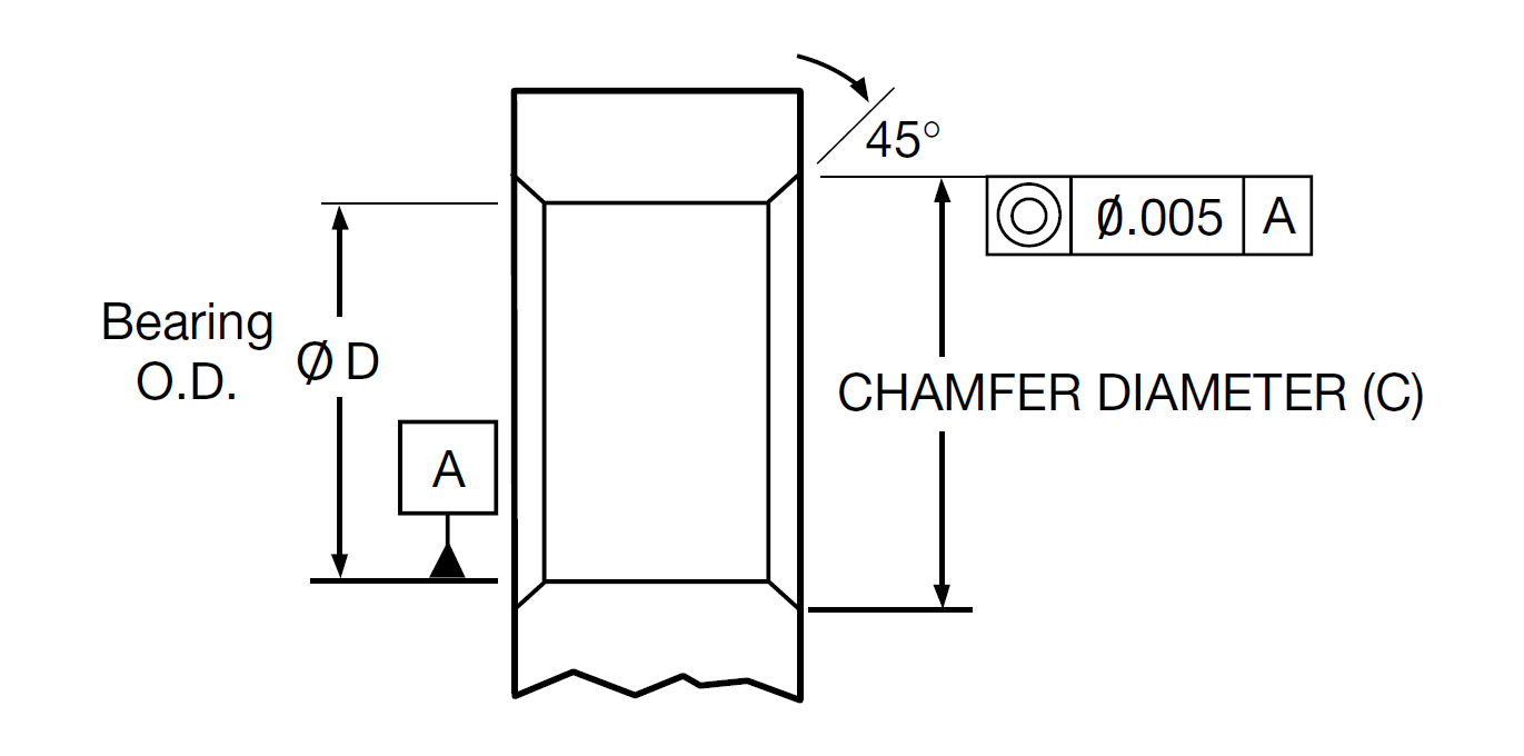
Chamfer Diameter
(C) = M+[T - H + (2 X E )]
(Tolerance + .008/-.007)
T = average housing thickness
H = average outer race thickness
E = average V-groove depth in race, depending
on groove
Housings
The housing into which the bearing is mounted must be designed to ensure the structural integrity of the bearing. The recommended housing dimensions are as follows:
- Bearing-to-housing fit: .0002 tight to .0008 loose.
- Bore finish: 32 Ra.
- Round within the bore diametral tolerance.
- Bore aligned perpendicular to housing faces within .002 for sleeve bearings only.
- Housing width: .005 tolerance (for staking purposes).
- For V-groove retention the housing bore is chamfered. Chamfer size is calculated as shown above.
- For housing stake and bolted plated retention, break edges .005 max on both sides.
The recommended shaft and housing sizes are based on an operating temperature range of -65° to 350°F. At elevated temperatures, allowances must be made for different coefficients of expansion for the various shaft, bearing, and housing materials. In general, the mating components should be adjusted to provide the recommended fit at operating temperature. In addition, internal bearing fit-up between the ball and race may be required (either additional internal clearance or decreased torque) to ensure proper operation over a broad temperature range.
The use of heavy interference fits between a bearing and housing is not generally recommended because it reduces internal clearance. If the application requires a heavy interference fit, the assembly of the bearing and housing must be accomplished by use of temperature differentials to prevent galling of the bearing or housing. The temperature differentials are dependent on the amount of press fit. After assembly, the bearing usually cannot be replaced because of galling during pushout. When using interference fits, the internal ball to race fit-up must allow for the contraction of the race (which can be up to 100% of the interference fit, depending on housing material, heat treatment, and size).
Corrosion Resistance
A bearing, housing, or shaft interface is a likely place for various forms of corrosion to develop. Corrosion may be initiated or accelerated by wear (fretting) or may be caused by the galvanic action of dissimilar metals in the presence of an electrolyte. Control of galvanic corrosion can be established by isolating and protecting the active metal surfaces. When corrosion resistant materials are used for bearings, pins or bolts, and housings, there is little problem with galvanic corrosion. When dissimilar, noncorrosion resistant materials are used, precautions must be taken to protect bearings, shafts, and housings used in contact with other metals or with the atmosphere.
The table below shows various bearing, shaft, and housing materials, with finishing precautions necessary to combine them to make a complete design. In addition to these recommendations, the bearing O.D. and housing bore are sometimes coated with zinc chromate primer according to TT-P-1757, epoxy primer according to MIL-PRF-23377, or sealant according to MIL-PRF-81733.
Treatments to Prevent Galvanic Corrosion
| Bearing Material (Bore and OD Surface) | Housing or Shaft Material | ||||
|---|---|---|---|---|---|
| Aluminum Alloys | Low Alloy Steels | Titanium | Corrosion Resistant Steels | Super-Alloys | |
| Aluminum alloys | A | A,C | A | A,C | A,C |
| Bronze and brass | A,C | C | S | S | S |
| Bronze and brass cadmium plated | A | C | — | S | S |
| 52100 and low alloy steels | A,C | C | — | C | C |
| 440C stainless steel | A,C | C | S | S | S |
| 440C with wet primer | A | C | S | S | S |
| Corrosion resistant steels, 300 series (17-4PH, 15-5PH, PH 13-8Mo, etc.) | A,C | C | S | S | S |
| Superalloys (Rene 41®, etc.) | A,C | C | S | S | S |
Letter Codes
— = incompatibleA = Anodize aluminum per MIL-A-8625, Type II, or Alodine per MIL-C-5541
C = Cadmium plate per Fed-Spec QQ-P-416
S = Satisfactory for use with no surface treatment required