Engineering Reference
Precision Ball & Roller Bearings
(Medium to Large Diameter)
Internal Geometry of Roller Bearings
In a cylindrical roller bearing running under a load, force is transmitted from one bearing ring to the other through the rolling elements. Even moderate loads can produce stresses of tens, even hundreds of thousands of pounds per square inch. These internal stresses have a significant impact on a bearing's life and performance. The concepts central to the internal bearing geometry of roller bearings are radial play, roller end play, and free angle of misalignment. We define these concepts below.
Design Analysis of Internal Bearing Geometry
When establishing the free state internal bearing geometry for roller bearings, the specific bearing application details must be carefully considered. These include the bearing loads (radial, axial and moment), speeds, operating temperature range, the specific geometry of the housing and shaft, their fits and the materials of which they are made. Proper bearing function is dependent on all of these variables. The extremes of each variable must be accounted for in the bearing design to ensure that the maximum and minimum installed internal bearing geometries result in optimal running conditions and maximum bearing life.
Radial Play
Radial play in roller bearing is similar to radial play in ball bearings. Like ball bearings, roller bearings are assembled with a slight amount of looseness between the rollers and raceways. This looseness, referred to as radial play, is defined as the maximum distance that one bearing ring can be displaced with respect to the other in a direction perpendicular to the bearing axis when the bearing is in an unmounted state (shown here).
Some general statements can be made about roller bearing radial play:
- Roller bearings are used for support of predominantly radial loads. Minimal thrust loading is tolerable, with a general guideline being 10% of the radial load.
- Ideally, a roller bearing will perform best with a minimum installed radial play. This ensures that the load is distributed among the maximum number of roller elements, thereby minimizing the stresses.
- Radial play is affected by any interference fit between the shaft and bearing I.D. or between the housing and bearing O.D.
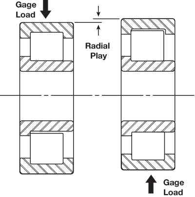
Radial play.
Roller End Play
With roller bearings, roller end play (a.k.a. axial play or roller to guide flange clearance) is completely independent of radial play. Roller end play is the maximum relative displacement of the roller element within the confines of the double guide flanged (u-shaped) ring. Close attention and control of end play is required to manage roller skewing and to provide for optimum tracking at all loads and speeds.
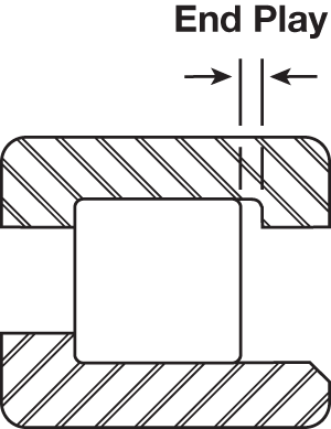
Roller end play.
Free Angle of Misalignment
Roller bearings have some capacity for misalignment. As a result of the previously described looseness, or play, which is purposely permitted to exist between the bearing components, the inner ring can be tilted a small amount in relation to the outer ring. This displacement is called free angle of misalignment. The amount of misalignment allowable in a given roller bearing is determined by its radial play, end play, guide flange angle and roller element geometry, namely the roller flat length and crown radius values (turn to Roller Bearing Features for more information). The misalignment capability of a roller bearing can have positive practical significance because it enables the bearing to accommodate small dimensional variations that may exist in associated shafts and housings. The performance of a misaligned roller bearing will be degraded to a certain extent, but for slight misalignments under reasonably light loads, the effects will not be significant in most cases. In general, the misalignment a bearing is subjected to should never exceed the bearing’s free angle of misalignment.
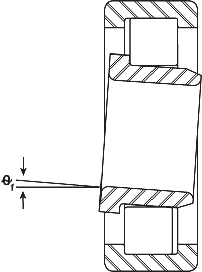
Free angle of misalignment.