Engineering Reference
Precision Ball & Roller Bearings
(Medium to Large Diameter)
Internal Geometry of Ball Bearings
Force is transmitted from one bearing ring to the other through the balls when a ball bearing is running under a load. The contact area between each ball and the rings is relatively small so that moderate loads can produce stresses of tens, even hundreds of thousands of pounds per square inch. Such intense internal stresses significantly impact a bearing's life and performance. Therefore, the internal geometry of a bearing—its radial play, raceway curvature, and contact angle—must be carefully chosen so loads will be distributed for optimal performance. Below we define the concepts related to internal geometry and provide you with formulas for calculating radial play, axial play, and contact angle.
Design Analysis of Internal Bearing Geometry
When establishing the free state internal bearing geometry for ball bearings, the specific bearing application details must be carefully considered. These include the bearing loads (radial, axial and moment), speeds, operating temperature range, the specific geometry of the housing and shaft, their fits and the materials of which they are made.
Proper bearing function is dependent on all of these variables. The extremes of each variable must be accounted for in the bearing design to ensure that the maximum and minimum installed internal bearing geometries result in optimal running conditions and maximum bearing life. Consult with NHBB’s Applications Engineering department for assistance with these special design details.
For any given bearing load in a ball bearing, internal stresses can be somewhat controlled by affecting the geometric relationship between the balls and raceways. When running under a load, force is transmitted from one bearing ring to the other through the ball set. Since the contact area between each ball and the rings is relatively small, even moderate loads can produce stresses of tens or even hundreds of thousands of pounds per square inch. Because internal stress levels have such an important effect on bearing life and performance, internal geometry must be carefully chosen for each application in order for bearing loads to be distributed properly.
Raceway, Track Diameter, and Track Radius
The raceway in a ball bearing is the circular groove formed in the outside surface of the inner ring and in the inside surface of the outer ring. When the rings are aligned, these grooves form a circular track that contains the ball set.
The track diameter and track radius are two dimensions that define the configuration of each raceway. Track diameter is the measurement of the diameter of the imaginary circle running around the deepest portion of the raceway, whether it is an inner or outer ring. This measurement is made along a line perpendicular to, and intersecting with, the axis of rotation.
Track radius describes the cross section of the arc formed by the raceway groove. It is measured when viewed in a direction perpendicular to the axis of rotation. In the context of ball bearing terminology, track radius has no mathematical relationship to track diameter. The distinction between the two is shown to the right.
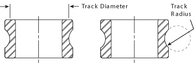
Raceway, track diameter, and track radius.
Radial and Axial Play
Most ball bearings are assembled in such a way that a slight amount of looseness exists between balls and raceways. This looseness is referred to as radial play and axial play. Radial play is the maximum distance that one bearing ring can be displaced with respect to the other in a direction perpendicular to the bearing axis when the bearing is in an unmounted state. Axial play, or end play, is the maximum relative displacement between the two rings of an unmounted ball bearing in the direction parallel to the bearing axis (shown to right).
Since radial play and axial play are both consequences of the same degree of looseness between the components in a ball bearing, they bear a mutual dependence. While this is true, both values are usually quite different in magnitude. Radial play can often vary between .0002" and .002", while axial play may range anywhere from .001" to .020".
In most ball bearing applications, radial play is functionally more critical than axial play. While radial play has become the standard purchasing specification, users may also specify axial play requirements. It must be kept in mind, however, that the values of radial play and axial play for any given bearing design are mathematically interdependent.
These general statements can be made about ball bearing radial play:
- The initial contact angle of the bearing is directly related to radial play—the higher the radial play, the higher the contact angle.
- For support of pure radial loads, a low contact angle is desirable.
- Where thrust loading is predominant, a higher contact angle (or radial play) is necessary.
- Radial play is affected by any interference fit between the shaft and bearing I.D. or between the housing and bearing O.D.
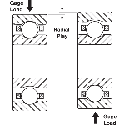
Radial play.
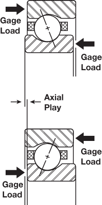
Axial play.
Track Curvature
Track curvature is an expression that defines the difference between the arc of the raceway’s track radius and the arc formed by the profile of the slightly smaller ball that runs in that raceway. It is simply the track radius of a bearing raceway expressed as a percentage of ball diameter. This number is a convenient index of “fit” between the raceway and ball, and is always slightly greater than the corresponding arc of the ball.
Track curvature values typically range from approximately 52% to 58%. The lower percentage, tight fitting curvatures are useful in applications where heavy loads are encountered while the higher percentage, loose curvatures are more suitable for torque-sensitive applications. Curvatures less than 52% are generally avoided because of excessive rolling friction that is caused by the tight conformity between the ball and raceway. Values above 58% are also avoided because of the high stress levels that can result from the small ball-to-raceway conformity at the contact area.
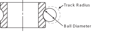
Track curvature.
Contact Angle
The contact angle is the angle between a plane perpendicular to the ball bearing axis and a line joining the two points where the ball makes contact with the inner and outer raceways. The contact angle of a ball bearing is determined by its free radial play value, as well as its inner and outer track curvatures.
The contact angle of thrust-loaded bearings provides an indication of ball position inside the raceways. When a thrust load is applied to a ball bearing, the balls will move away from the median planes of the raceways and assume positions somewhere between the deepest portions of the raceways and their edges. The following drawing illustrates the concept of contact angle by showing a cross sectional view of a ball bearing that is loaded in pure thrust.
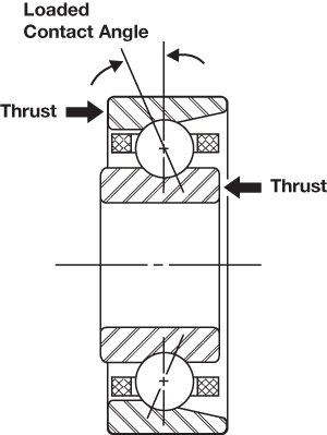
Contact angle.
Calculating Radial Play, Axial Play and Contact Angle
Radial Play
PD = 2Bd (1 – cos β0)
PD = 2Bd – √((2Bd)2 – P2E)
Axial Play
PE = 2Bd sin β0
PE = √(4BdPD – P2D)
Contact Angle
β0 = cos–1 (2Bd – PD / 2Bd)
β0 = sin–1 PE / 2Bd
PD = Radial play
PE = Axial play
β0 = Contact angle
B = Total curvature = (fi + fo – 1)
fi = Inner ring curvature*
fo = Outer ring curvature*
d = Ball diameter
* Expressed as the ratio of race radius to ball diameter.
Free Angle of Misalignment
As a result of axial and radial play, which is purposely permitted to exist between the components of most ball bearings, the inner ring can be tilted a small amount in relation to the outer ring. This displacement is called free angle of misalignment. The amount of misalignment allowable in a given ball bearing is determined by its radial play and track curvature values. The misalignment capability of a bearing can have positive practical significance because it enables a ball bearing to accommodate small dimensional variations that may exist in associated shafts and housings. The performance of a misaligned bearing will be degraded to a certain extent, but for slight misalignments under reasonably light loads the effects will not be significant in most cases. This concept is shown to the right. In general, the misalignment a bearing is subjected to due to the shaft and housing’s physical arrangement should never exceed the bearing’s free angle of misalignment.
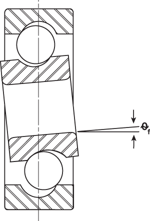
Free angle of misalignment.